Showing posts with label Pump. Show all posts

Minimum Flow System


My friend, In this posting we will discuss about the pump recycle systems. The pump shall be protected from minimum flow, due to the following reasons;
1. Thermal consideration which has effect to the pump efficiency (The efficiency will decrease significantly at low flow)
2. At low flow, Internal recirculation will be occurred
3. Increase load impeller (both axial and radial)
4. liquid containing a large amount of abrasive particles must flow continuously through the pump. at low flow, the particles can circulate inside the pump and erode the impeller.

The three types of pump recycle systems which are generally applied are ; 
1. Continuous recycle system --> use Orifice
2. Control loop system and --> use Control Valve
3. Automatic recycle system. --> use ARC
My friend, The followings are short guidance to apply those types.

1. ORIFICE
  •  This system will provide continuous recycle flow whenever pump is running, regardless of the process demand.
  • Typically applied for pump below 50 hp (38kW), or small capacity.
  • Don’t forget, you must consider the additional capacity of the pump (the capacity is included recycle flow)
  • For initial estimation, 30% of rated flow can be used as recycle flow basis.
  • Take care for high pressure drop condition, is there any flashing? Two phase? Or vibration? If two phases is occurred, the orifice should be located at the end of the recycle line.


2. CONTROL VALVE
  • When the minimum flow is reached, the valve start to open. The flowmeter shall be located at pump discharge side (installing at suction side will decrease the suction pressure, decrease NPSHa )
  • The flow meter should be located before(upstream the) recycle line connection.
  • Be careful with high pressure drop, control valve may be noise and vibration (an orifice in series with the control valve may be required)p


3. AUTOMATIC RECIRCULATION 
  • This type is the spring loaded, combined recycle and check valve
  • The spring loaded is set at a pressure correspond to minimum flow (based on pump curve) where the recycle starts to open.
  • Check this link for the detail how the ARC valve work.
  • No need additional check valve in the discharge system. The ARC provides back flow protection.
  • Take care with pump with high discharge pressure ( while low pressure source) . The orifice may be required at the recycle line to avoid very big change of momentum

General Guide.
  • Recycle line should be routed back to the source (tank or vessel) NOT to pump suction. Bubble of two phases can be formed during pressure reduction by orifice or control valve. It may be introduced into the pump. 
  • Routing to suction line may causes excessive temperature build up in a very short time.
  • For 2 x 100% operation, the recycle line can be connected at combined line.
  • For 2 x 50 % operation, each pump shall have its own recycle system.


-          

     Generally, the recycle system is not shown in the PFD. There are two specific pumps when a recycle system should be included in the PFD. These are the BFW pump and pump with the high head or capacity. (discharge pressure > 1000 psig)


That's all I can share this time.
Hopefully this is useful for you..

Wait ..wait..I have a question for you.
Here my simple question.
Let say, 100 gpm liquid shall be transferred via pump to a tank. The recycle is continuous of 30 gpm use orifice.

How you state the pump capacity in the process datasheet?
A. Normal = 100 gpm , Rated = 100 +30 = 130 gpm
B. Normal = 130 gpm, Rated = 130 x 1.1 = 143 gpm
C. Normal = 100 gpm, Rated = 1.1 x 100 + 30 = 140 gpm

hhmm,,,can you explain WHY ?  it is simple, isn't ? :D

Thank my friend..
Share:

Discharge Pump System


My friend, how are you today, ? I hope this weekend give us the best of everything ; find some good experiences, new spirit, and (may be) new planning for the better future, etc.
My friends, Let me share a simple material regarding the discharge pump system, but in this posting, I will only focus on centrifugal pump type. 

The followings are the points to be considered when we design centrifugal pump discharge system. Hope this article help you in checking P&ID.. 

1. Provide  block valve for isolate the discharge side

The block valve or isolation valve  will be used for :
   - Priming and regulating flow
   - Isolating the pump for inspection and maintenance
The type of block valve can be either gate valve, ball valve or butterfly valve type depends on the piping specification.

2. Provide a pressure gauge (PG or PI) to verify the discharge pressure

The pressure gauge should be located close to the outlet of the pump. It will help you diagnose pump system problem. The pump head can be determined based on the pressure gauge at suction and discharge pump. But the static head shall be counted for correction.

3. Provide check valve to protect the pump 

The check valve will protect the pump in the event of sudden stoppage that cause reversal flow in an upset condition. Without check valve, pump may running in reverse direction, pump shafts have been broken this way. 
The following picture is a sample of discharge pump system.


 An example of typical system which potential cause back flow or reverse flow.

My friends, the following is just an example, of course it is not a real condition . I want to explain this as simple as possible. hopefully, you can imagine the back flow or water hammer phenomenon more easily.
The pump deliver liquid through high elevation to the destination which is lower than the highest point. The liquid will flow back to the pump when upset condition or sudden pump stop.


In the system above, when start up water hammer can be occurred. It is suggestion to install manual valve that are controlled to open gradually.

4. Control valve SHALL be located at discharge pump

Control valve in the suction side cause pump work in unstable condition, also will cause more pressure drop to suction system, and finally decrease the NPSH.


5. Provide minimum flow to protect the pump

Centrifugal pumps should not be used at a low flowrate less than a certain percentage of BEP ( Best Efficiency Point). Generally the minimum flowrate required for centrifugal pump may be in range 50%-70% of BEP.
Usually, in the design basic stage, or proposal stage we assume of 30% of rated flow. This assumption shall be updated in project or detail engineering stage based on vendor information and pump performance curve.

Hopefully we can discuss more deep about the minimum flow of centrifugal pump in other time. the following is just an example.


The system can use RO or control valve or automatic recirculation valve (ARC).
The rule of thumb say that the control valve system typically becomes economical above 50 hp ( 38 kW) and the RO applied for pumps below 50 hp (38 kW). 

My friends, thank for reading.
I will very appreciate you if you give me comment or correction when I make any mistakes in this posting.

Hope this useful for you. .

Happy weekend,..,,
Share:

Reducer Suction Pump System


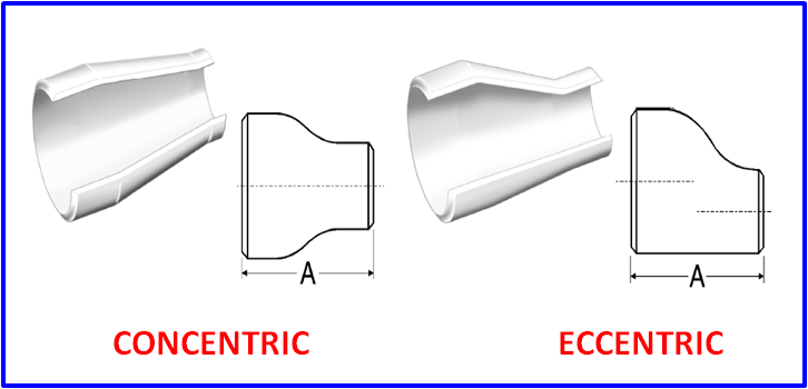
Generally, the pump inlet nozzle size is smaller than the suction line size. Therefore, usually, the reducer is required on suction pump nozzle. What the appropriate type of reducer should be applied ? Eccentric or Concentric ?

In this posting, I will share my experience in determining what reducer type should be used, whether it is eccentric or concentric ?
Hopefully, the following picture give you better understanding what the consideration in selection. 


You can refer to this link for check the availability of reducer size based on ANSI B16.9.

1. Suction Pump 

Eccentric type, TOP Flat is selected for suction pump.

Suction pump service fluid is liquid. To avoid build up vapor or bubble in the system, the eccentric type with TOP FLAT should be used.

2. Steam Flow 

To avoid condensate accumulated which might will be potential cause slug flow, the eccentric, BOTTOM Flat type shall be used.

3. Flare Header

The flare header pipe shall be sloped to Flare KO Drum. The liquid formed along the pipe shall free draining to the KO Drum. Therefore, the appropriate type of reducer type is eccentric with BOTTOM flat.

My friends, That's all I can share .. 
What do you think ? what the appropriate type of reducer should be applied on control valves?
Share:

Pump Suction Strainer


For pump protection, inlet line suction pump should be fitted with a strainer. The strainer can be either T or Y type, permanent or only for temporary. For clean fluid service, such as; demineralized water, boiler feed water, etc the temporary strainer can be used..

In this posting, we will discuss about the strainer installed in suction pump. My friends please talk back in the comment if I mistake and let me know your opinion.  If you have any other information regarding the strainer, please share in the comment section

1.Generally, for permanent application, Y type strainer is used for small size.

The following table can be used as a general rule of thumb ;

Suction Line Size            Type
3” and smaller                        Y 
4” and larger                           T 

(This rule depends on particular project requirement. Please Note: The piping specification shall be followed instead of this rule).

You can click here to see the picture of T and Y type.


2. Permanent strainer shall be provided in service where fouling or solids or foreign matter are normal part of the pumped fluid.

3. Temporary strainer can be applied for clean fluid service, for example; boiler feed water, demineralized water etc. Suction pump shall be provided with temporary strainer where permanent strainer is not provided

4. Strainer shall be located as close to the pump as feasible, and at downstream of suction block valve. 


5. Piping Engineer shall be design the system arrangement, so that the strainer element can be easily inserted and removed without effecting the pump alignment.

6. If the Y type strainer is located at a low point, a ¾” valve drain can be provided at the Y type strainer flange of 3” and larger 


7.  Strainer can be equipped with a pressure differential gauge to monitor pressure drop of the strainer.


8. If required, A pressure gauge shall be provided downstream of a permanent strainer and temperature gauge shall be located at upstream of strainer.


9. Temporary strainer is always used to prevent damage when commissioning

My friends, That's all I can share .. 
Actually, I can't explain WHY the TEE type strainer is applied for larger size ?.( why the Y strainer is generally applied for small size?) 
If you have the answer or any explanation, please share in comment section below.

I believe you  know much rather than me. So please add any other information about strainer in pump suction if you know..

Happy holiday my friends ^_^ ,,  I hope this holiday brings you the best of everything...
Share:

Suction Pump Block Valve

Block valve shall be provided on suction and discharge line of pump. The block valve is required for isolation purpose during maintenance. In this posting, we will discuss about the block valve on suction pump. The block valve is not required for suction pump where pump maintenance can be performed without isolating the suction side.

The following drawings are example of application the block valve on suction pump. 

1. Block valve is normally installed for isolating the suction side


2. Where pump maintenance can be performed without isolating the suction side, suction block valve is no longer required


3. For high pressure service, generally consider high rating 900# or more, double block is required.


4. In case using spectacle blind is selected for isolation instead of double block, spectacle blind shall be installed downstream of the valve


5. For pump require “AUTO START” , the suction block valve shall be locked open (LO), for example ; Boiler Feed Water Pump, Surface Condenser Condensate Pump, Compressor Lube Oil Pump etc.


6. For stand by pump, suction valve should be in normally open position. As a standard operating practice/procedure, stand by pump should be in a stand by condition with liquid filled in the pump and with suction valve in open position.


That's all I can share .. Please correct me if I'm wrong (cmiiw)
Share: