Showing posts with label PSV. Show all posts

PSV Installation-Guide

My friend, Let me share a simple material about PSV installation. However it will only focus on designing the system.  This is become my first posting in this year. Hopefully, this material is useful for you in developing the system around PSV.

My friends, in developing or reviewing the P&ID, especially in PSV system, please consider the following ;

1. PSV normally be installed close to protected equipment.
The safety valve is installed for protecting the equipment, so that the closer to the equipment is better. For example, from safety point of view, to install the PSV directly at vessel is better than at line outlet vapor.

2. PSV for vapor application at vessel -shall be connected to the vessel in the vapor space higher than HHLL.

3. If any demister, PSV shall be connected to the vessel  at below the demister since there is  any potential blockage of demister, and if the PSV be installed at downstream demister, it will not protect the vessel in that case.


4. PSV may be installed at outlet vapor line. For this case, take care with the 3% pressure drop limitation.


5. For inlet line, please consider the total pressure drop of inlet line less than 3% of set pressure of the PSV.
This requirement (3%) is to avoid chattering on PSV. 

6. Inlet PSV shall "free draining" to avoid liquid accumulation. 
Please consider put NOTE on the P&ID, and as process engineer, you should check the final design by Piping engineer.


7. Block valve at inlet line ( if any) shall be LO and LC for spare PSV.
Block valve at outlet line (if any ) shall be LO


8. if discharged to ATM ( please indicate on P&ID "ASL" (at safe location) instead of ATM). The block valve is not required. The weep hole to be provided at lowest point of discharge pipe to drain the liquid.


9. Outlet line to be designed with Mach No < 0.7 
Check the momentum ( Rho v2 ) if the value of (Rho v2) > 200.000 Pa..please take care since it may be vibration. Usually Piping engineer will also check the requirement of piping support.
Back pressure to be considered based on PSV type.
Noise for emergency case typically more than 85 dB is still accepted. 
Check the two phase flow pattern, if there is any slug flow - please take care, you must state in the P&ID so that Piping Engineer will consider the strengthening of support.

10. Outlet line shall only have downward elevation change to the flare sub-header.  

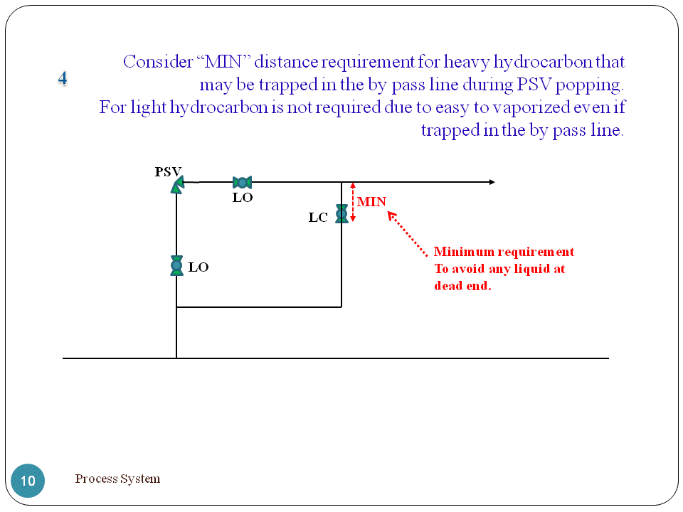
11. Consider minimum distance from by pass block valve to discharge line for heavy hydrocarbon service.

12. Lateral connection to be designed with 45 deg or 30 deg to the header.


13 Please consider, Other system may have specific requirement. Think about it by yourself. 


I think that all, that I can share to you by today.

My friend, how are you today? It’s been long time I don’t update my blog, really sorry guys. I was very busy doing my project – urea plant in Palembang. Thank you very much for many of you who've contacted me via email and give me feedback and much-much spirit for me to keep updating this blog ‘again’

Thank so much for support me guys, I love you.

I hope this weekend give you all the best of everything,

Share:

Relieving Condition Exceed Design Temperature

Equipment design temperature is usually determined based on the maximum temperature plus a certain margin. The margin could be different for each project, say 20F, 25 F or 30F. Conducting rigorous simulation for fire case, the temperature in each stage simulation is set higher than the previous stage by certain interval. Let say, using 10F in interval temperature will result in temperature about 30F higher than the operating temperature at third stage simulation. That is why; relieving temperature for fire case is very often higher than the design temperature. Whether or not increasing rating pipe is required?.

PSV Doesn't Provide Adequate Protection of Fire Case

See the picture below

A Separator has operating temperature of 120 F with design temperature of 145F. Looking at simulation above, in only two stages of temperature increase, the temperature will reach 150F.

After fire, the temperature will increase commonly above the design temperature. And even in some cases, the vessel could rupture before increasing pressure reaches PSV’s setting pressure. In other word, the vessel will have ruptured before the PSV open. Thus, the PSV doesn’t provide adequate protection for the vessel in case of fire.

For example, the following picture show that the metal plate temperature reaches 1200 F in only 15 minutes after fire.
That is, actually, the PSV doesn’t provide adequate protection for the vessel in case of fire. Therefore, some other options for vessel protection from fire case beside the PSV should be considered, such as: 1. Depressuring 2. External cooling 3. External insulation 4. Provide proper drainage

My friend, for now, we already know the fact that PSV will not give adequate protection for vessel in fire case. But, why do we always provide PSV as protection devise of the vessel? Why do we consider for fire case too? That could be a joke, right? In my opinion, that is all to meet the CODE requirement
My friend, a note shall be made, although the relieving temperature is higher than the design temperature, and the PSV is not efficient to protect the vessel against fire, the PSV remain to be designed based on the relieving temperature, since the PSV is installed as a safe guard

Example Case

I still remember, one of our friends has ever asked me; at that time, he did calculation of fire case for instrument air receiver, the relieving temperature was exceeding the maximum allowable for 150# rating pipe. The question was, whether the 150# pipe rating of inlet PSV would be needed to be increased to 300# or not?

Of course NOT, the pipe rating class of 150# does not need to be increased to 300#, since the determination of pipe rating shall based on maximum condition without consider fire case.

Besides that, it is not common to design PSV for instrument air system with fire case. Personally, I prefer calculate the PSV load of instrument air receiver based on blocked outlet case (if it is possible). Furthermore, In some cases, it might not be applicable to size PSV of instrument air receiver based on fire case. Actually, it shall be based on FERA (Fire and Explosion Risk Assessment) justification whether the instrument air receiver included in fire zone or not.

The block outlet case has more possibility occurred than the fire case. Based on my experience, the load of block outlet is also smaller than un-wetted fire case. Therefore, it is better to design PSV of instrument air based on block outlet case than fire case. Moreover, if you still design PSV based on fire case to consider worst case load, that PSV will not provide adequate protection for the vessel: D.

Do you agree with me, don't you?

Talk back in comment section below and let me know your opinion !
Share:

Rigorous Method for Fire Case

In previous article, I have explained that relieving load for fire case can be calculated as heat input divided by latent heat of vaporization. (W = Q/Hv). The heat input have been discussed before, see fire case –heat input rate. The latent heat of vaporization is rather difficult to be determined. During fire, liquid in the vessel will be vaporized, but the amount of vapor formed is not fixed, because the liquid composition is change overtime. In this article, I will explain you step by step the rigorous method for fire case

Let imagine the system consist of a three phase separator below, the fire case calculation procedure is as follow;

1. Determine the inventory volume of isolated system, both for condensate, water, and gas based on actual size of the vessel and pipe.

2. Calculate the wetted area.


3. Perform simulation:

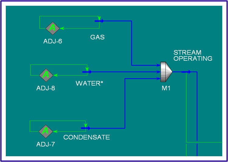
a. Define stream for WATER, CONDENSATE, and GAS. Input composition, pressure, and temperature as operating condition of the three phase separator.

b. Adjust mass flow for those streams, to achieve actual volume for each stream in accordance with inventory volume calculation (1). Mix those streams to be STREAM OPERATING

c. (a) and (b) is model of the separator at normal operating condition based on actual condition.


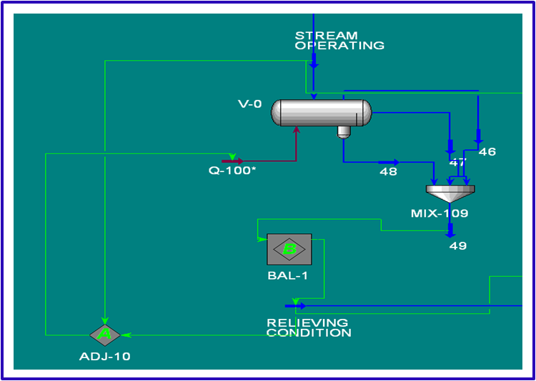
d. Install three phase separator, V-0. The STREAM OPERATING is as inlet stream to the separator. Adjust Q-100 (heat input to vessel) to achieve pressure RELIEVING CONDITION

(e). The temperature and pressure will increase to initial RELIEVING CONDITION due to fire. (This simulation assumes the PSV instantly reach relieving condition after opening). The outlet stream from separator is mixed.

e. Balance the mixing stream (d) to stream RELIEVING CONDITION. Input the pressure of relieving pressure value (=1.21 x set pressure).

f. (d) and (e) is model of the separator at relieving condition as initial stage which is PSV will start open


g. Install a three phase separator (V-1). The stream RELIEVING CONDITION (e) is as inlet stream to the separator.

h. Heat input due to fire case is calculated by increasing temperature with interval 10 F. Thus, set the temperature outlet separator (V-1) of 10 F higher than the RELIEVING CONDITION.

i. The outlet stream is CONDENSATE 2, WATER 2 and VAPOR. The VAPOR will be divided into two streams, LOAD STAGE 1 and VAPOR 2

j. Mix CONDENSATE 2, WATER 2 and VAPOR 2 to be INLET STAGE 2.

k. Adjust mass flow rate of VAPOR 2 to achieve actual volume flow of INLET STAGE 2 is equal with initial actual volume STREAM OPERATING.

l. The stream LOAD STAGE 1 is relieving load fire case


m. The heat input to V-1 in HYSYS simulation is Q-1 BTU/hr, whereas the actual heat input is Q API = 21.000 F A ^0.82 BTU/hr

n. Calculate the required time of increasing temperature at stage 1, that Is (Q-1) / (21.000 F.A ^0.82)

o. Install a three phase separator V-2. The stream INLET STAGE 2 is as inlet stream to the separator.

p. Repeat the procedure from (g) to (n), for stage 2, stage 3, stage 4 ....with temperature is increased by 10F in every stage. We can stop the procedure if the cumulative time is one hour (it’s assumed that the fire has been suppressed during 1 hr, you can use more than 1 hour if you want)

q. Calculate the required area for each stage, (with the relieving load are LOAD SATGE 1, LOAD STAGE 2, LOAD STAGE 3, …)

r. Use the stage requiring the maximum orifice area as basis datasheet of the PSV.

finish :D


Good morning my friend, That's all I can share today, … I’m very happy today because I find a new spirit for better life. Don't regret what was loss; it didn't disappear actually, just in use by more appropriate user to make it more useful thing. Sometimes we lose something, but at the same time, we get the other thing that better, at least a lesson.

Hopefully you never bored with my article.

Thank for reading,.

Share:

Fire Case - Heat Input Rate

Fire can cause overpressure of storage or vessel. Either liquid vaporization of wetted vessel or vapor expansion of unwetted vessel due to heat input will increase the pressure. Heat input rate of fire exposure is not calculable from standard of heat transfer fundamental. Fortunately, OSHA regulations specify standards which are to be followed for particular material in storage vessel and API also provides formulas for calculating heat input rate which are to be followed for particular condition of process vessel.

The following picture presents OSHA Venting Requirement of Fire Exposure to Storage Vessel.


For flammable and combustible liquid, heat input refers to NFPA 30 as follow.

Note :

1. Information in table applies to liquified components ; see original standard for nonliquified gases

2. CGA = Compressed Gas Association
NFPA = National Fire Protection Association
ANSI = American National Standard Association

3.Heat Input expressed in BTU/hr, with area in square feet.

4.See source documents for details of area calculations

My friend, if you want to check the correctness of value in above table, please refers to original reference, Guidelines for Pressure Relief and Effluent Handling System, AMERICAN INSTITUTE OF CHEMICAL ENGINEERS (AICHE), Table 3.3-1 (page 131 of 538). You can find that book in our library.

API STD 521 provides formulas for calculating heat input rate to process vessel containing liquid.
Q = 21.000 FA^0.82

Where adequate drainage and firefighting equipment do not exist, equation below should be used,
Q = 34,500 FA^0.82

Regarding a drainage, as long as the amount of liquid which is spilled out around the vessel is possibly decrease, use the first formula ( = heat flux 21000).

F is environment factor. The value F = 1 for bare vessel. Refer to API STD 521 Table 5 (page 17) for other than bare vessel.
A is wetted area of the vessel.

The value of A ^0.82 reflect that not 100% vessel area exposed by fire. It is true for large vessel, for small vessel, we can use assumption that 100 % vessel area is totally exposed by fire.

For example, for small bare vessel, the equation to be Q = 21.000 A.

My friend, please note, based on the formula, when 82% fraction area is applied the heat flux is 21.000 BTU/ft^1.64/hr or 34500 BTU/ft^1.64/hr. And when 100% fraction area is applied, the unit will be BTU/ft^2/hr. This understanding will useful in perform depressuring simulation using HYSYS.

The above formula is for pool fire case which has heat flux of 21.000 BTU/ft1.64/hr. Whereas, based on API STD 521, the heat flux for jet fire is 95.500 BTU/ft2/hr (average). From the unit of heat flux for jet fire, its show that 100% fraction area is used (for jet fire is localized heat flux).

Hope this drawing helps you get better understanding of pool fire and jet fire


And below is jet fire


My friend, in this posting we discuss about heat input rate of fire exposure for process vessel. The following are the important point,

1. For adequate drainage and fire fighting exist, use formula Q = 21.000 FA^0.82

2. For small vessel, use 100% fraction area is exposed by fire, therefore Q =21.000 FA. In my understanding, vessel with wetted area less than 200 ft2 can be considered small vessel (see NFPA 30)

3. For wetted vessel, overpressure caused by liquid evaporation, the relieving load capacity can be calculated as heat input divided by latent heat of vaporization. (W = Q/Hv).

4. Heat flux of jet fire is very high (95.500 BTU/ft2/hr average), and in localized area.

5. I suggest you to sizing PSV on fire case for pool fire case only.

6. The relieving temperature can be higher than the vessel collapse temperature. Vessel will collapse before increasing pressure reach PSV’s set pressure. Therefore, actually, PSV doesn’t provide sufficient protection. Depressuring is one of the additional protections against fire. (We will discuss about fire case depressuring both for pool and jet fire in other posting)

My friend, thank you for reading, please correct me if I'am Wrong.
Share:

Reflux Failure Case

Reflux failure case is the major case of all tower or column. Reflux failure can be caused by the following:
- Power failure lead to reflux pump off
- Pump failure
- Control valve failure ( fail closed or stuck closed)
- Operator error etc

When reflux pump fail, there no reflux flow inlet to column. Basically the reflux flow is flown back to column (at rectifying section) to increase separation efficiency. Other that, the reflux flow is useful also for cooling the vapor flow to the top of the column. Reflux pump failure cause ‘Loss of Cooling’, as a consequence, the vapor temperature will not be cooled down and overpressure will occur.

Control valve failure has same effect as a pump failure.

Power failure case cause trip of the air cooler, cooling failure and overpressure will occur.


Based on my experience, the simplification of the calculation load capacity for reflux failure has been made. 2nd tray vapor flow is assumed as basis load capacity. In HYSYS, the column model never convergent if the reflux flow = 0, therefore in HYSYS simulation, input reflux flow with very small number. After column model convergent, we can use 2nd tray vapor flow as load capacity of the PSV.

Actually, the determining load capacity of reflux failure is very complex. Let imagine, once the pressure increase in the column, the boiling point of fluid in the reboiler increase, the number of vapor will decrease. It has many effects to separation and equilibrium condition.

I have found much discussion regarding reflux failure case, especially the method for determining load capacity. Unfortunately, until now, there is no agreement reached, no method fixed, therefore I can’t make a justification which one is the best approach for calculating load capacity for reflux failure.

Please follow the following link for more discussion about reflux failure
1.Discussion 1 from Cheresources
2.Discussion 2 from Cheresources
3.A sample dynamic method for determining load capacity reflux failure

My friend, please share to me if you have other method for calculating load capacity for reflux failure case

Thank for reading, hopefully this posting useful for you

Best regard and thank you

Share:

Tube Rupture Case

Tube rupture may be occurred for shell and tube heat exchanger type. Based on my experience, some design philosophy using 2/3 rule, and some other using 10/13 rule for the criteria of requirement PSV for tube rupture. Which one is correct? Should we apply 2/3 or 10/13 rule?

Tube rupture is possible cause overpressure in shell and tube heat exchanger type if Test Pressure of Low Pressure Side LESS than design pressure of High Pressure Side. That is where 2/3 and 10/13 rule coming from. For equipment with test pressure = 1, 5 x design pressure, the 2/3 (=10/15) rule is applied, whereas for test pressure = 1, 3 x design pressure, the 10/13 rule is applied

When tube ruptures, fluid will flow from high pressure side to low pressure side. Check whether increasing pressure at low pressure side due to tube rupture possible exceeds the corrected test pressure or not. If YES, the tube rupture case applicable to be considered

My friend, do you know, why API STD 521 use term corrected test pressure to evaluate the possibility of overpressure due to tube rupture? hydrotest pressure is conducted at ambient temperature, therefore the correction is required because tube rupture is not occurred at ambient temperature.

The corrected test pressure can be calculated with this following formula.

Allowance stress at ambient temperature > allowance stress at elevated temperature, therefore from above formula, corrected hydrotest pressure > uncorrected hydrotest pressure. In other word, we can use uncorrected hydrotest pressure for checking whether tube rupture is applicable to be considered or not. This understanding is very useful, especially when we don’t have the data of allowance stress.

Hopefully this picture gives a simple explanation.

Thank for reading, hopefully this posting useful for you

Have a great day…

Share:

Blowdown PSV

I can't sleep again, till this midnight , almost 00.00 PM (or AM ? ), I just confuse what to do. I think it will better for me to do something useful. But what ? I don't get any idea. Until finally, I remember this blog.
My blog save my brain :D.

Usually, when I don't know what to do, the most often I decide is check my facebook, just want to know my friend's status.

Oh My God,,why I share my feeling to you.,I should share my knowledge instead of my feeling, right ? I am so sorry.

My friend,there are many terminology related to PSV. I give you a summary as following picture.


Please comment to this posting for only item which you don't understand :D,
I will answer your question later.

ho,, ho,, sorry for this disappointed posting,,hopefully you understand me, I am afraid will make many mistakes explanation in this midnight.

Okay,,I give one item only. I will explain you about BLOWDOWN.

Blowdown is differential pressure (can be in percentage) between set pressure and re-seat pressure. PSV start to open at set pressure and will 100% back closed at re-seat pressure. What do you think, why the re seat pressure lower than set pressure ? and What impact blowdown value to PSV's operation ?

See the picture below

And this picture below will show why the re seat pressure is lower than set pressure.

uhhh..sorry my friend,. This article is considered complete although there is still many question about blowdown which may be raised up. How blowdown can be adjusted to ovoid chattering. What the relation between blowdown and 3% pressure drop limitation at inlet pipe. How about blowdown for Pilot type PSV..etc and may be you have several other question also.

But Sorry my friend, I will sleep,,,let continue in other opportunity...

don't forget to pray each other my friend, pray before we sleep


Thank you -Domo arigatogozaimasu-

Share:

Gas Blowby Case

Gas Blowby is the discharge of gas from a process component through a liquid outlet. It can be caused;
- Failure of a liquid level control system.
- Or in advertent opening of the control valve by pass.

One of the effects of gas blow by can be overpressure in a downstream component. Of course, the low level is the detectable condition that indicates gas blowby may be occurred.

This picture below show gas blowby case

For instance in a separator system, to determine whether this case applicable or not, check design pressure of the equipment in downstream control valve. If the design pressure is equal, the gas blowby will not cause overpressure in the downstream equipment. Conversely, If the design pressure of the downstream equipment is lower than the upstream equipment, when control valve fail, the gas will flow to the downstream equipment and cause overpressure.

Please note, gas blowby case is applicable if only the design pressure of downstream equipment lower than the upsteam pressure.

The required load capacity of PSV can be determined based on the mass balance in the system after control valve fail is occurred.

Here is just simple case.

The most often questions which is raised by new process engineer in calculation load capacity gas blowby is the formula for determining the maximum flow through the control valve

The maximum flow through control valve is depends on the control valve Cv and the pressure drop across the control valve. The following picture show an example formula from one of control valve Vendor; please note, each Vendor has their own formula that might different in each other. I give this formula to show you what the variable that has affect to flowrate through the control valve

My friend, for detail calculation in project stage, I suggest you to use INSTRUCAL software for determining the maximum flow through the control valve.

After the maximum flow through control valve is calculated, the required capacity of PSV at downstream equipment can be calculated (for simple, Load = Maximum flow stream 3 – Normal flow stream 4)

Thank you for reading my friend, that’s all I can share to you today. Correct me if I am wrong…

" Selamat liburan panjang :D , semoga ada pencerahan hidup yg bermanfaat yang kita dapatkan... ( don't know how to express this in english :D) "

Share:

Block Outlet Case

My friend, regarding the overpressure protection system design, one of important responsibility for process engineer is determining the cause of overpressure. In this posting, we will discuss whether a kind of case is possible occurred.

There are many causes of overpressure. Every possible overpressure condition shall be reviewed to ensure overpressure protection device capacity is adequate to protect the system. The following picture presents the causes of overpressure.


My friend, let discuss how block outlet is applicable to be considered.
(other cases in next posting.)


BLOCKED OUTLET

For review whether this case applicable or not, check : is there any valve that possible closed? Or any control valves which is ‘fail to close’ position? is there any object that possible block the fluid flow ? If YES, it may be blocked and lead to pressure increase.

The required load capacity of PSV can be determined based on the mass balance in the system after block outlet occurred.

Here is just simple case.


For system which comprises of many vessel / separator with same design pressure, block outlet case is only considered for PSV in the most upstream location. When block outlet occurred at downstream the system pressure increase lead to open PSV at the upstream.

I think, it is better to explain by this picture


Therefore, for system with same design pressure, the block outlet only applicable for one PSV only.

My friend, that’s all, I can share to you today. Hopefully, this simple article useful for you.
Tomorrow is 6 April 2012, that is holiday for all of us;
I just want to say, happy holiday my friend, God bless you all.,,

Share:

Accumulation and Overpressure

In this posting, we will discuss about pressure level related to relief valve, especially the difference between accumulation and overpressure. Those two terminologies (accumulation and overpressure) often cause some engineer confused.

Accumulation is pressure above the maximum allowable working pressure of the vessel. Overpressure is pressure above the setting pressure of the relief valve. When we say ‘accumulation’, its mean we are talking about the vessel, and when we say ‘overpressure’, we are talking about the pressure relief valve

For better understanding, see this picture


The pressure level of the vessel is presented in the following picture.


See above picture,, for non fire case, the increasing pressure of the vessel with MAWP 100 psig is allowed up to 110 psig (the allowable pressure is 116 psig if multiple overpressure protection devises are installed). That is the cause; the PSV shall be set at 100 psig and shall have relieving pressure 110 psig (or 116 psig for multiple PSV)to protect the vessel.
See the picture below


Thank my friend,hopefully this posting give better understanding why the PSV is set at 100 %MAWP and the max relieving at 110%,116% or 121%. That all because the PSV is used to protect the vessel.

Share:

PSV Sizing

Sizing of pressure relief valve is clearly explained in API STD 520 part 1. Some formula is provided for calculation the orifice size either for vapor or liquid application, critical or non critical condition.

My friend, there is no difficult thing in sizing PSV as long as all data required is already provided. The all we need is just inputting the data in the formula or in the spreadsheet :D , then select the appropriate standard orifice size ( refer to API STD 526)

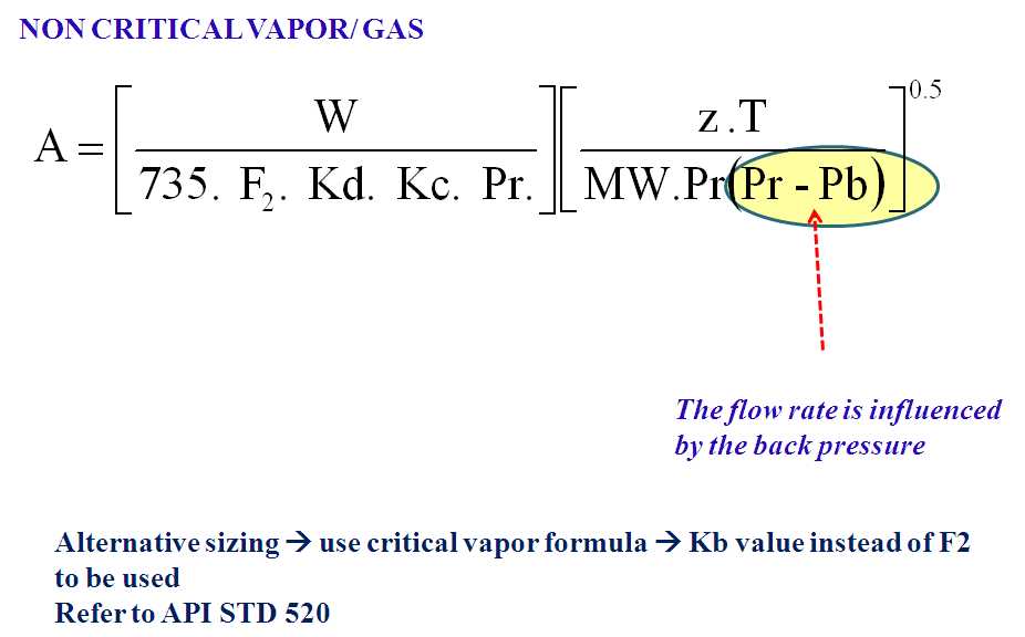
The following pictures, show the formula in API STD 520


For non critical condition, the outlet pressure has impact in sizing orifice area but for critical condition is not. In critical condition, the outlet pressure is lower than the critical flow pressure therefore there will be no impact to the sizing.

Note this, in critical condition, the flow through the nozzle will be influenced by the inlet pressure (relieving pressure). In non critical condition, the flow will depend on the differential pressure between inlet and outlet. (Relieving pressure – back pressure).
Use correct formula !

For you who looking for the sizing example, click the following link.
1. Gas/Vapor Critical and an example from Leser
2. Gas Subcritical and an example from Leser
3. Steam and an example from Leser
4. Liquid, an example from Leser

Thank you for your attention.

Share:

Built Up Back Pressure Calculation


My friend, do you still remember? One of consideration in selection of relief valve type is built up back pressure. In this article I will explain you how to calculate the built up back pressure. Oh, do you still remember what is built up back pressure? Is it a constant or variable?

Built up back pressure is pressure at outlet PSV in open mode, a variable back pressure since it is depend on the relieving flow. Read my previous post about back pressure for more detail in built up and superimposed back pressure
In this explanation I use a general flare system which the disposal is discharged to atmosphere via flare stack. Let imagine, when relief valve open, relieving fluid flow thru Tail Pipe –Sub Header – Main Header-Flare Drum-Seal Water Drum – Flare Stack – Flare Tip and finally discharged to atmosphere at certain height ( for safe disposal purpose)
The Built up back pressure can be calculated by count up total pressure drop at the pipe, drum, stack and tip. Start calculation from the pressure drop at the tip, then at stack until tail pipe of the relief valve. The built up back pressure is pressure that exist at outlet relief valve ( that is same as with total pressure drop from the tail pipe to the flare tip)
For more clear, see this picture below


To calculate the back pressure of the PSV, determine the pressure drop at tip, stack, Water Seal, KOD and pressure drop along the pipe from point 2 to point 7. Since the pressure at outlet tip is atmospheric pressure condition, we can calculate the pressure at outlet PSV, which is a total pressure drop along the system from point 1 to point 7.
The basis back pressure calculation is rated flow. Rated flow is flow rate based on actual orifice area of PSV. My friend, once the back pressure is calculated, then we can determine the PSV type. For built up back pressure less than 10% of PSV’s set pressure, a conventional type can be used. Balance below type can be used for back pressure up to 30%, and pilot type shall be used for higher back pressure. Note shall be made, even though the selection of PSV type is based on the back pressure consideration, it is not the only consideration in PSV selection
After the back pressure calculated, we can also check the fluid condition due to decreasing pressure from inlet PSV (relieving pressure) to outlet PSV (back pressure) using HYSYS simulator. Is hydrate formed there? is the icing occurred? And for liquid phase, is the liquid will be flashed?
The back pressure calculation is so simple, isn’t? How about if there is any PSV open simultaneously? The difference is only the combined flowrate from others PSV shall be considered in pressure drop calculation. Hopefully this picture help you more understand with the concept of back pressure calculation.


<< correction : W3 at above picture shall be 1200 lb/hr instead of 1500lb/hr>>

See the picture above. I will explain you why the calculation of built up back pressure is very important not only for PSV design but also for flare system design. Let imagine;
- PSV 01 is set at 50 psig with relieving flow of 200 lb/hr.
- PSV 02 is set at 100 psig with relieving flow of 1000 lb/hr.
In case the two PSV open simultaneously, what do you think what happen with the PSV 01 if the back pressure of PSV 02 is more than 50 psig? Of course the PSV 01 cannot open properly
What is the solution? Hmm,, look at this picture, it will show you a better configuration of flare header system to avoid that condition


<< correction : W3 at above picture shall be 1200 lb/hr instead of 1500lb/hr>>

The other options are increase the flare header size or provide 2 flare header for high pressure and and low pressure separately.
The above sample is a very simple case. Sometimes, for instance in power failure case, there is many PSV will open at the same time. The back pressure for each PSV shall be checked to ensure each PSV can properly operated. The back pressure profile of each PSV can be used to determine the configuration of the flare system
My friend, that’s all, I can share to you. Hopefully, this topic reminds us that the back pressure is something very important to be considered both in PSV and flare system design

Thank you for your attention.


Share: